When I tackle a machine on my bench for full restoration, I take apart every single piece. Clean, sand, polish every screw. Extreme? Yep! But that's why I take so much pride when my machines leave my shop! I keep everything for each machine separate and in their own trays, cups, area. EXCEPT when they are all my personal stock! This past winter I had some time in between customer machines, for a change, to work on some of my stock machines. I decided to tackle a handful of 201-2's at the same time. (NOTE: if a part varied on a machine (ie Chrome verses Black hand wheel, blackside parts, etc. - I kept a log to ensure that the original pieces went back to the machines they came from) Not that anyone would truly notice the difference mind you...but authenticity is important to me. Anyway - I digress.
 |
| Pieces & Parts for FIVE Singer 201-2's |
 |
| Lotsa motors to go with all the parts |
Phew! It took an entire weekend to take all those machines apart! Some parts had to be oiled, penetrated...coaxed to separate from the head. And at Midnight on a Sunday night, it's time to go to bed and head to work in the morning. I'm excited to get right back to it after work! The phone rings on Monday, some friends want to go out - ok! Tuesday - big outage at work, gotta work late. Wednesday - flat tire Thursday - what a week! Netflix and Wine! Friday - a Sit N Sew with all the Gurlz!! Woo Hoo! Maybe next weekend I'll get back to the boxes of parts. Well you get the idea. I'd love to tout that I can leisurely work on these babies 24\7 but alas, I still work full time at an 8-5 job, have family and friends, and lookee there - I'm a human being and get tired!
I thought it was a GREAT idea to tackle multiple machines at once. And I still do, to a certain degree. But when customer machines still come in, and orders, sometimes it's just this nagging "I have GOT to find the time to finish ALL of those!" Over the next few months, I took a small tray of parts at a time and got to work. Cleaning, dremeling, polishing, wiping, inspecting...every piece, until I could finally say all the parts were ready to go back on the heads. Whoops....gotta do the motors. You can see the process of cleaning and re-wiring those babies here
 |
| After cleaning, polishing |
Don't even get me started on what it takes to clean the head - we'll get to that on another post. Today, I want to point out what to do and look for when your trays and stuff have been moved around 42 times and you aren't 100% sure which screws go where! Unless of course you have a fully intact machine sitting next to them all. (Whew - thank goodness I do!) But when I DON'T - here's a reference for which screw is which! Along with the part names & Numbers according to Singer for easy look up! We're just going to focus on the Presser bar area in this example. I threw the stop motion clamp & screw in there because the screw looks similar to the others. Until you look closer!
 |
| Screws are different but VERY similar |
 |
Tension Releasing Lever & Hinge Screw
Ref Singer No's 32573, 97
Thinner and smaller diameter than the Presser Foot Lifter Hinge Screw
10mm in length - 5mm diameter on the head
|
 |
Presser Bar Lifter & Hinge Screw
Ref Singer No's 66564, 85
Fatter and shorter than the Tension Releasing Lever Hinge Screw
12mm in length - 8mm diameter on the head
|
 |
Clamp Stop Motion Clamp Screw & Stop motion screw
Ref Singer No's 51280, 45294, 45295, 45336 Screw - 246
11mm in length - 4mm diameter on the head - 3mm unthreaded at the bottom
|
 |
| Tension Releasing Lever & Presser Foot Lifter |
Next - we focus on getting the presser bar back in. You'll need the Presser Bar Guide Bracket, set screw and the actual Presser Bar.
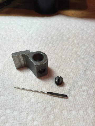 |
| Presser Bar Guide Bracket & Set Screw Ref Singer No 45237, 453 |
 |
| Presser Bar Guide Bracket & Set Screw Ref Singer No 45237, 453 |
 |
| Presser Bar & Presser Guide Bracket |
Slide the Presser Bar Spring right through the top until it rests on the Presser Bar Guide Bracket
 |
| Presser Bar Spring Ref Singer No 32675 |
 |
| Pressure Regulating Thumb Screw and Washer Ref Singer No's 51228. 66773, 66772 |
 |
| Presser Bar back together |
Almost done! Don't forget to add the thread cutter back onto the bottom of the bar before you add your presser foot!
 |
| Thread Cutter Ref Singer No. 26075 |
The thumb screw that measures a little more than 1/2" in diameter and 3/4" in length is the one for the presser feet as well as the shiny side cover on the back of the machine. The one that is a little LESS than 1/2" in diameter and 1/2" in length is the one for the Faceplate! Regardless - they are all threaded the same on the screw, other than the feed dog lever, so it's easy to put them in the wrong place.
