Showing posts with label Vintage Sewing Machines. Show all posts

Monday, June 19, 2017

Remove (and put back) the Hook on Singer 66 99

Time for a little VISUAL help with these old service\adjusters manuals.   I have a tendency to look up everything and anything when I'm working on a machine.   And frankly, I'm tired of thinking, now where did I put that file??   So I'm making my own adjusters manual.  LOL  Kind of.

Remove (and put back) the Hook on Singer 66 99
Text reads:
To Remove the Sewing Hook
1) Remove the oscillating hook slide, presser foot, throat plate and bobbin case.
Note: if you are working on a REAL OLD 66, like from a treadle cabinet - the bobbin case is a bit more difficult to remove.   It will come out easier in step 3.


2) Turn the machine over on its hinges, take out the screw (N, Fig 8) and remove the feed dog. (I use Chapman Bit #93)


3) Also loosen the set screw (P, Fig 8) and lift out the bobbin case position bracket (F, Fig 5).

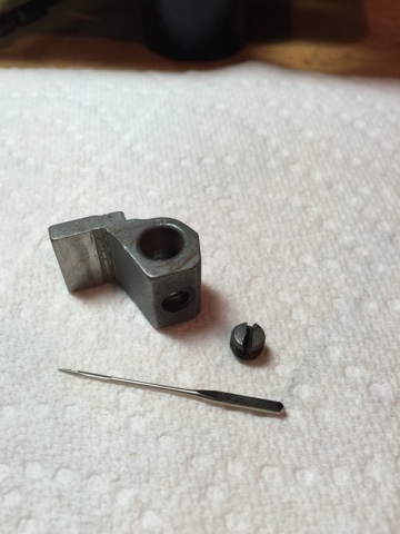
First item to note here - is that there are TWO versions of the bobbin case position bracket. So it's not going to make any sense if you are working on a hundred year old machine. See the picture below to understand the difference.


So this step is valid on a Model 99 and later Model 66's.  Solid Hand Wheel is a good rule of thumb here.   If it's a solid wheel - there is a set screw under the machine bed that releases the riveted Pin seating the bobbin case position bracket.  The next photo is the set screw they are talking about.  If that set screw isn't on your machine, then you are looking at the OLDER model, which I'll get into after.


So if you SEE this set screw - you'd need to loosen (or I would remove personally, so I can stick oil, PB Blaster or whatever it takes to get all that gunk out of there) to release the Bobbin case position bracket.  Once that set screw is super loose (or out) the bracket will come out. (yeah right).   I stick a screwdriver under it and gently pry it up.  After this is all clean - it's a moot point.   It drops in easily and you just turn that set screw back in to tighten it.  It's the dirt, grime, dust bunnies, etc that makes it seem difficult to get out.

The position pin on the bottom of the part goes into a hole under the hook.  The "Set Screw" under the bed is what holds it in place.

With the OLDER model 66's, with a spoked hand wheel, there's no set screw under the hook area.  It has a SOLID position finger that does NOT move and one screw that holds it down in there, instead of a riveted pin and set screw.  Most manuals tell you to move over the position finger to get the bobbin case out.    With this model - you can't.   You have to remove the entire bracket to get the bobbin case out.  I use a Chapman Bit #90 here.


4) Loosen the oscillating hook crank clamping screw (O, Fig 8)

5) Also loosen the presser bar bracket screw (M, Fig7) and raise the presser bar high enough to permit the sewing hook to be lifted from the machine.

This is another one of those steps that makes me chuckle.   Such a simple sentence but SOOOO much work to make it happen after these old girls have been neglected for so long.....

So let me show you what screw they are talking about.   The circled screw is the one that needs to be loosened.   I use Chapman Bit #25.

Do yourself a favor and lubricate this area REALLY well before you go after the presser bar bracket screw (blue circle).    I keep mentioning the Chapman Bits because they are, in my humble opinion, the most perfect fit on Singer Screws.


The bit fills the slot on the top of the screw so perfectly that unless you are being REALLY careless, you will avoid stripping the top of any screw.   But I digress.   The important thing to note here is that even if you get that set screw loose....that presser bar isn't going to move without some work.   Lubricate with oil, PB Blaster if needed.  The presser bar needs to be able to move up quite a bit to give the hook clearance to lift out.   I also unscrew the Presser Bar Pressure screw (blue arrow) up at the top as far as it will go.   If you take the Presser bar Pressure Screw OUT - watch you don't lose the washer that is right underneath it.  Below is a picture to give you an idea of how much clearance you need to get the hook out.


So after ALL of that...let's talk about how to ACTUALLY get that hook out.  Because you are probably looking at that picture and asking yourself.. "How in the hell did she do that??  That thing is NOT moving!"

Yeah - more lubrication, PB Blaster, etc.  Take a look at the next photo if you can't get it out.  The RED circle is the oil hole for the hook.   Load that hole up good.  The BLUE arrow is the screw that you loosened in Step 4.   It's what clamps that piece onto the very bottom of the hook.  If it's not loose enough - it's not going to go anywhere.   The GREEN arrow is the end of a screwdriver pointing at the bottom of the hook piece.   You can gently tap the handle end of a screwdriver to try to get it to move a little more.


Putting it all back:

So HOURS and HOURS later, after you have cleaned all the new areas you can get to and all the parts you removed, we want to put it back together.  Well it's not just put everything back where you found it.   We have a few things to tweak:

- We need to "time" the hook so that it will sew again!
- We need the feed dogs to be where we want them to be!
- We need that presser bar back in the right position and make sure our presser foot isn't crooked and applies pressure appropriately!

1)  Put the hook back in the machine.    Turn the balance wheel until the needle bar is in the lowest position.  Put the hook in so that the hook tip is right around where the tip of the needle will be. (Don't worry - we will adjust this more precisely when we "time" the machine.)


Make sure the bottom end of the hook goes back into that clamp underneath. Then gently tighten that clamping screw so that it grips the base of the hook to now turn when you turn the balance wheel.


2) Put the Bobbin Case Position Bracket back in the machine. Note: if you are working on the older model like i am - you will remove this again after the machine is in "time" and shimmy that bobbin case back in later.

If you are working on the more common model, you put the pin on the bottom of the bracket in the hole and tighten the set screw underneath the bed of the machine.


Thursday, June 15, 2017

Remove (and put back) Feed Fork Connection Singer 66 99

So I'm working on a Singer 66 Red Eye.  I want to remove the Feed Fork Connection so I can CLEAN it!
Note: these instructions relate to Singer 99, 127 and 128 as well.

This machine, like many vintage machines that have been sitting in God knows where for 50-60 years, has so much GUNK and rust just caked onto all the metal that I had to take it apart down to the Head. This post is to remind me (and help you) figure out how I took this thing apart and how to get it back together so I don't have to re-invent the wheel (figuratively speaking) the next time I do this.   I usually don't need to take them apart this far, but this was an extreme case.  So without further delay...here's how to "Remove (and put back) the Feed Fork connection" 

Let's first identify some parts:

insert feed fork pic

insert feed rock shaft

Here's the text from an old adjuster's manual with HORRIBLE pictures.

 STEP 1: "To remove the feed fork connection, first remove the eccentric screw C2 (see pic 1) and nut D2 (see pic 1), disengaging the feed fork connection N2 (see pic 1), from the feed rock shaft O2, (see pic 1)."

Ok - so how...why, what???  The pic they have is a pencil drawing of the entire underbody of the machine..   NOT HELPFUL.   So here's the real deal. Put the machine in front of you on a table so you are looking at the BACK of the machine.   Lay it down gently with the front of the machine to the tabletop, exposing her underbelly.   Bottom left corner of the machine is where the Feed Fork Connection is connected on the bottom.    We need to release the fork from the bottom first.

Get yourself a 3/8 wrench to fit over the nut on the right side

Using your right hand, put the wrench over the nut so that you can hold it in place.

Using your Left Hand, fit the appropriate sized screwdriver to fit perfectly in the slot of the eccentric screw that is securing the Feed Fork Connection to the Feed Rock Shaft.  Note: I use Chapman bits - #98 is pretty close
Once the nut is removed, the eccentric screw will not come out until you remove the screw that tightens around the "eccentric" part of the screw!

Three pieces removed to get the end of the Feed Fork Connection Loose on the bottom
Ok great - Step 1 is done.   What's next?

STEP 2: "Loosen the thumb screw J2, (see pic), turn the arm side cover up, as shown in Fig 43, and retighten the thumb screw J2."

Yet more terrible pictures.  So what are they saying??

Open the back cover.... or remove it
This next part just cracked me up...

Step 3: "Loosen the set screw K2, Fig 45, in the feed cam and move the feed cam Q3, Fig 45, toward the arm rock shaft F3. Fig 45.   Remove the feed fork connection N2, Fig 45 and roller P2, Fig 45."
Here's the image they provide.  A Skeleton pic - with no head.   Yeah...

So what does that step really entail?   Why?  How?  "MOVE the feed cam??"   You're kidding right?
So this sent me on a search through my files for a parts list with pictures of the part.   This thing is so dark and filthy I can hardly SEE screws or anything else in there!   And there's a cast iron WALL blocking me from pulling the fork out....it doesn't bend people. Who WROTE this thing??   And there's a Stitch Length knob in there and pieces attached to the side??   Hello?

Ok - so again, here's the real deal:

The  "K2 Set Screw" is the screw in the feed cam. 
So here's where I kinda started scratching my head and laughing.   I tried a screw driver and a small hammer.   They said the feed cam moves....   uh....no it doesn't.   Is it supposed to?  Does it really need to?    So I tried wriggling the Feed Fork Connection out ignoring that part....cuz it definitely doesn't move...    I scratch my head some more....   Finally I look up the feed cam in an old parts manual to see what the part looks like....

Feed Cam
Well lookit that...   it's a separate part.   Not a great image, but it helped me figure out that that eccentric tear drop side on the left will likely need to be pointing down in order for the fork to come out.    That's helpful, but the Feed Fork has a piece sticking out that is engaged into the Stitch Length knob on the front.  That thing is NOT coming out without moving the feed cam, that's for sure.

I looked closely at the set screw I took out - it's got a pointed tip, that goes into the groove on the main shaft to hold it in place!  


Well I'll tell you what, I don't think that set screw was necessary after all these years, because that thing is ON there.   With Rust, crud and God knows what else...   So to MOVE the Feed Cam...here's the "real deal".    PB Blaster....Oil - cleaner, Q-tips, whatever you can get in there.    You gotta get that crub gooey to get her moving.    It's the only way.   After you get it nice and gooey (I let PB Blaster soak in under that groove for about 15 minutes) THEN.....Get out some Locking Pliers (Vice Grips)!!!

Important!  Wrap the metal you are securing and moving.  Slippage will cause DAMAGE!  I locked the main shaft with one pair and gave it a confident turn on the Feed Cam with another pair.

Feed Cam flush against the Feed Fork Connection prior to moving the Feed Cam towards the Main shaft.

Feed Cam moved about 1/4" towards the shaft AFTER lubrication and careful turning with 2 pairs of vice grips.  See how the groove on the main shaft doesn't line up with the set screw hole anymore?   It really does move!
Once I got that feed cam spinning freely - I was able to move it over just enough to give me some wiggle room with the other end of the Feed Fork Connection.    You've got to be able to angle the fork enough to get the "ROLLER" that they mention out of the Stitch Length Regulator slideway piece that is screwed onto the inside of the head!

From the bottom, grab the end of the Feed Fork Connection and bring it up to the backside of the head

Turn that Feed Cam so that the teardrop shape is pointed down.  You have to shimmy that ROLLER that is attached to the Feed Fork Connection OUT of the Stitch Length Regulator piece before it will come out of the bottom.  TIP : The Stitch Regulator screw on the front of the machine should only show about 3 or 4 threads, this is a good position to get that roller free.

Once you clear the roller out of the slideway on the stitch regulator and position the Feed Cam just right to get it out, there is one little sweet spot (turning and shimmying) that will let it free and you can pull it out of the bottom of the Head.

Here's the "FREED" Feed Fork Connection with the Roller removed off of the center Pin. YUCK!

At this point - of course, I'm going to take all the Stitch regulator pieces out and clean those too.

Remove Hinge Screw, washer, Feed Regulator and the big ol screw knob on the front.
You might be wondering at this point why I didn't tell you to take the Stitch Length Regulator out before the fork.   Well, you gotta put the Stitch Length Regulator back in FIRST, so all the work to move the feed cam was necessary anyway.


IMPORTANT NOTE - Be sure there is SOME play between the feed cam and the Feed connecting fork!    It machine feels like it's "binding" - this might be too tight.


Sunday, April 3, 2016

Putting the Presser Bar back together on a Singer 201-2

I've found that I have a LOT of bookmarks that are valuable resources to Servicing and Restoring Old Singer Sewing Machines.   Some of which I find myself referencing over and over again. As well as reorganizing over and over again!   The biggest downside to using someone else's notes & references are that they are never in the order that I need, when I need it.  They are also missing my personal experiences and observations.  And God forbid....what if they take their blog\site down???   I better start making some of my own posts!

When I tackle a machine on my bench for full restoration, I take apart every single piece.   Clean, sand, polish every screw.  Extreme?  Yep!   But that's why I take so much pride when my machines leave my shop!  I keep everything for each machine separate and in their own trays, cups, area. EXCEPT when they are all my personal stock!  This past winter I had some time in between customer machines, for a change, to work on some of my stock machines.   I decided to tackle a handful of 201-2's at the same time.   (NOTE: if a part varied on a machine (ie Chrome verses Black hand wheel, blackside parts, etc. - I kept a log to ensure that the original pieces went back to the machines they came from)  Not that anyone would truly notice the difference mind you...but authenticity is important to me.   Anyway - I digress.

Pieces & Parts for FIVE Singer 201-2's
Lotsa motors to go with all the parts 
Phew!   It took an entire weekend to take all those machines apart!   Some parts had to be oiled, penetrated...coaxed to separate from the head.   And at Midnight on a Sunday night, it's time to go to bed and head to work in the morning.   I'm excited to get right back to it after work!   The phone rings on Monday, some friends want to go out - ok!   Tuesday - big outage at work, gotta work late.  Wednesday - flat tire    Thursday - what a week!   Netflix and Wine!    Friday - a Sit N Sew with all the Gurlz!!   Woo Hoo!    Maybe next weekend I'll get back to the boxes of parts.    Well you get the idea.   I'd love to tout that I can leisurely work on these babies 24\7 but alas, I still work full time at an 8-5 job, have family and friends, and lookee there - I'm a human being and get tired!   

I thought it was a GREAT idea to tackle multiple machines at once.   And I still do, to a certain degree.   But when customer machines still come in, and orders, sometimes it's just this nagging "I have GOT to find the time to finish ALL of those!"   Over the next few months, I took a small tray of parts at a time and got to work.    Cleaning, dremeling, polishing, wiping, inspecting...every piece, until I could finally say all the parts were ready to go back on the heads.    Whoops....gotta do the motors.   You can see the process of cleaning and re-wiring those babies here

After cleaning, polishing
Don't even get me started on what it takes to clean the head - we'll get to that on another post.  Today, I want to point out what to do and look for when your trays and stuff have been moved around 42 times and you aren't 100% sure which screws go where!   Unless of course you have a fully intact machine sitting next to them all.   (Whew - thank goodness I do!)  But when I DON'T - here's a reference for which screw is which! Along with the part names & Numbers according to Singer for easy look up!   We're just going to focus on the Presser bar area in this example.  I threw the stop motion clamp & screw in there because the screw looks similar to the others.   Until you look closer!

Screws are different but VERY similar
Let's start with the screws that go with the Clamp Stop Motion Screw, Tensioner release lever and Presser foot lifter.   2 of these screws are what are called "HINGE" screws.  They are called Hinge screws because the parts that are held onto the machine move freely on the screw.   That's what the little solid part above the threads of the screw are for!   I put a sewing machine needle in the individual photos to help decipher the size.

Tension Releasing Lever & Hinge Screw 
Ref Singer No's 32573, 97
Thinner and smaller diameter than the Presser Foot Lifter Hinge Screw
10mm in length - 5mm diameter on the head
Presser Bar Lifter & Hinge Screw 
Ref Singer No's  66564, 85
Fatter and shorter than the Tension Releasing Lever Hinge Screw
12mm in length - 8mm diameter on the head
Clamp Stop Motion Clamp Screw  & Stop motion screw 
Ref Singer No's 51280, 45294, 45295, 45336   Screw - 246
11mm in length - 4mm diameter on the head - 3mm unthreaded at the bottom
Tension Releasing Lever & Presser Foot Lifter
Above is a visual of WHY these two parts need "HINGE" screws.   Both of these parts need to be able to "rock" freely on the shiny smooth portion just under the head of the screw.   If they aren't working in unison together, one of those screws aren't seated correctly.  This is just one example of WHY I take everything apart.   Those "hinges" should get a drop of oil, and with a drop of oil can lead to build up and prohibit "smooth" hinges!   Also - when you are putting this area back together, the Tension Releasing Lever should go in first, then the Presser Foot Lifter.

Next - we focus on getting the presser bar back in.  You'll need the Presser Bar Guide Bracket, set screw and the actual Presser Bar.
Presser Bar Guide Bracket & Set Screw
Ref Singer No 45237, 453

Presser Bar Guide Bracket & Set Screw
Ref Singer No 45237, 453
Roll the hand wheel until the needle is the down position - this gets the gears out of the way so that you can "side-shimmy" that piece back in above the Presser Foot Lifter Level.   DO NOT FORCE THIS PIECE.   There is a sweet spot where this piece slides right in.  This piece is another area that needs to always move FREELY - Up and down with the presser foot lever.  Hold the guide bracket in place with your fingers (with the set screw out far enough to not impede the inside of the bracket) and slide that presser bar down through the top - through the bracket (held by your fingers), and down through to the bed of the machine.  

Presser Bar & Presser Guide Bracket
Note - you can tighten the set screw on the presser bar guide bracket enough to hold it in place for now, but plan on going back to it later.   For later reference when doing final TWEAKS - Presser foot height needs to be set at not more than 19/64 of an inch between presser foot and the top surface of the throat plate.  The presser foot should be parallel with the feed dog when lowered. The needle should be close to (but not touch) the inner or right hand side of the large toe of the presser foot.

Slide the Presser Bar Spring right through the top until it rests on the Presser Bar Guide Bracket
Presser Bar Spring
Ref Singer No 32675
Then you add the Pressure Regulating Thumb Screw AND THE THIN WASHER to the top to keep all the pieces in!
Pressure Regulating Thumb Screw and Washer
Ref Singer No's 51228. 66773, 66772
Presser Bar back together
Almost done!   Don't forget to add the thread cutter back onto the bottom of the bar before you add your presser foot!

Thread Cutter
Ref Singer No. 26075
Now the most interesting part I found I needed to research was for that thumb screw that holds the foot on!   I honestly thought the thumb screws were all interchangeable.   But then again, I had never piled all the parts for multiple machines into trays before.    Interesting findings!

The thumb screw that measures a little more than 1/2" in diameter and 3/4" in length is the one for the presser feet as well as the shiny side cover on the back of the machine.   The one that is a little LESS than 1/2" in diameter and 1/2" in length is the one for the Faceplate!  Regardless - they are all threaded the same on the screw, other than the feed dog lever, so it's easy to put them in the wrong place.